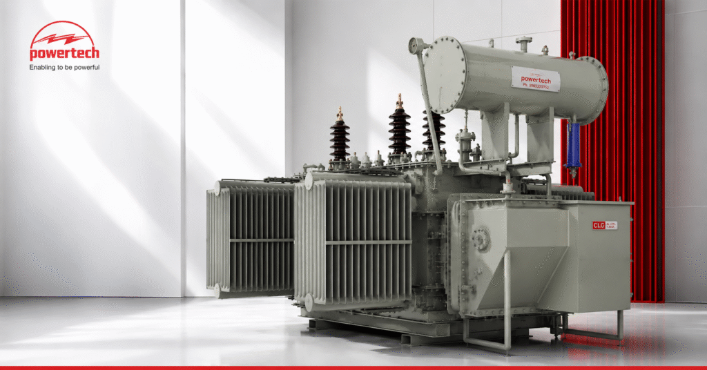
Power transformers are the silent backbone of modern industry. Every manufacturing plant, commercial complex, solar project, and utility network relies on them to transfer electrical energy safely and efficiently.
As Power Transformer Manufacturers in Hyderabad, one of the most common questions we receive from engineers, procurement teams, and project consultants is simple:
“How exactly does a transformer work if there are no moving parts?”
The answer lies in one of the most important discoveries in electrical engineering — electromagnetic induction.
In this guide, we’ll break down how a Power Transformer works, the science behind it, different core and winding designs, cooling systems, and where these transformers are used in real industrial environments.
Introduction to Power Transformers
A power transformer is an electrical device that transfers electrical energy between circuits using magnetic induction while changing voltage levels.
Its primary purpose is simple:
- Increase voltage for efficient transmission.
- Reduce voltage for safe industrial and commercial usage.
- Minimize transmission losses across long distances.
Without transformers, transmitting electricity over hundreds of kilometers would be economically impossible due to massive power losses.
Today, transformer efficiencies regularly exceed 98%, making them among the most efficient electrical machines ever developed.
Faraday’s Law of Electromagnetic Induction
Understanding how a transformer works starts with understanding Faraday’s Law.
The law states:
A changing magnetic field inside a conductor induces an electromotive force (EMF).
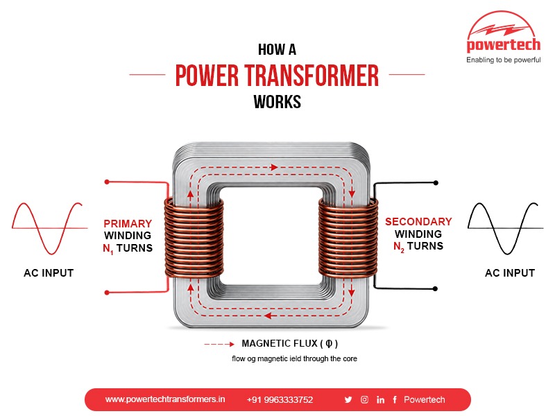
When alternating current flows through the primary winding, it creates a continuously changing magnetic field inside the transformer core.
This magnetic flux travels through the core and intersects with the secondary winding, inducing voltage in the secondary circuit.
The simplified transformer equation is:
Vp / Vs = Np / Ns
Where:
- Vp = Primary Voltage
- Vs = Secondary Voltage
- Np = Number of Primary Turns
- Ns = Number of Secondary Turns
If the secondary winding has more turns than the primary winding, voltage increases.
If it has fewer turns, voltage decreases.
This entire process occurs without any physical electrical connection between the windings.
That is the beauty of transformer technology.
Transformer Core Types
The transformer core provides the magnetic path required for energy transfer.
Different applications require different core designs.
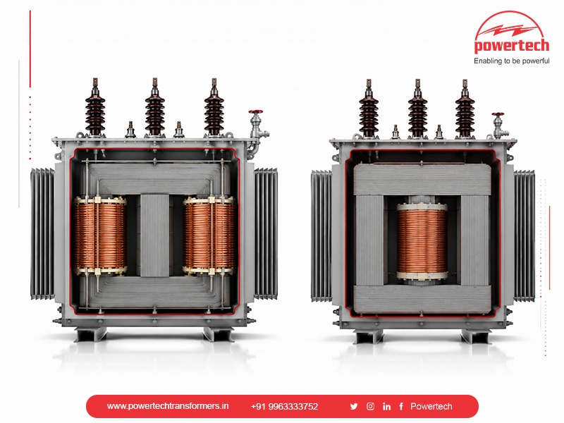
Core Type Transformer
In a core type transformer, the windings surround the core.
Advantages include:
- Better cooling characteristics
- Easier maintenance
- Suitable for large power ratings
These are commonly used in utility substations and industrial plants.
Shell Type Transformer
In shell type designs, the core surrounds the windings.
Benefits include:
- Improved short circuit strength
- Better mechanical protection
- Lower leakage flux
These are frequently selected for applications requiring higher fault withstand capability.
Amorphous Core Transformers
Modern energy-efficient systems increasingly use amorphous metal cores.
Compared to traditional CRGO steel cores, they can reduce no-load losses by up to 70%, making them attractive for utilities focused on reducing lifecycle operating costs.
Transformer Winding Types
The winding design directly impacts efficiency, losses, and thermal performance.
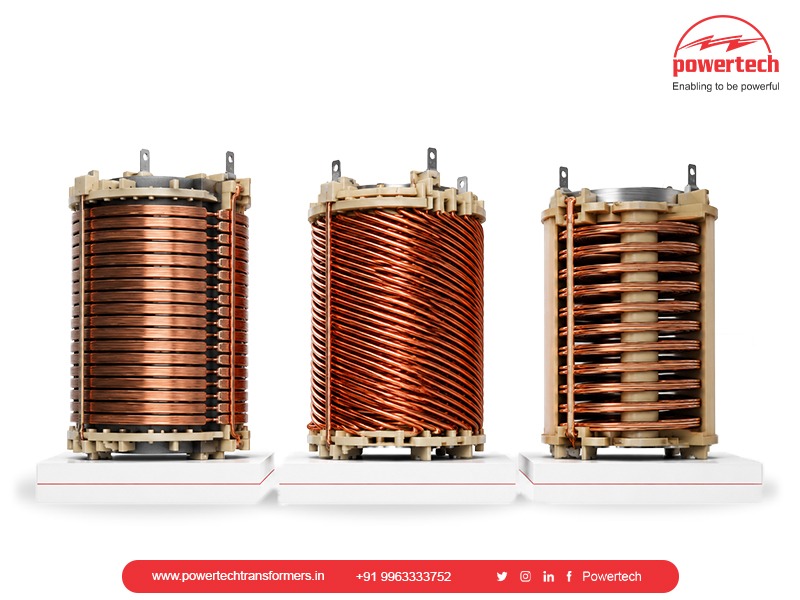
Layer Windings
Used for low-voltage applications where insulation requirements are moderate.
Helical Windings
Typically used in high-current applications due to superior mechanical strength.
Disc Windings
Common in high-voltage power transformers because they offer:
- Excellent impulse strength
- Better cooling performance
- Improved voltage distribution
At Powertech, winding selection depends on load profile, fault levels, ambient conditions, and customer application requirements rather than using a one-size-fits-all approach.
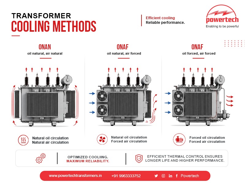
Transformer Cooling Methods
Although transformers have no moving mechanical parts, they generate heat continuously.
Effective cooling is essential for long service life.
ONAN — Oil Natural Air Natural
The most common cooling method for distribution transformers.
Heat dissipates naturally through transformer oil and surrounding air.
ONAF — Oil Natural Air Forced
Cooling fans increase heat dissipation capacity.
Ideal for higher loading conditions.
OFAF — Oil Forced Air Forced
Pumps circulate oil while fans improve cooling efficiency.
Often used in larger industrial transformers.
OFWF — Oil Forced Water Forced
Typically used in very high-capacity utility transformers where cooling requirements are extreme.
A useful rule engineers often follow:
Every 6°C rise above recommended operating temperature can significantly reduce insulation life expectancy.
Proper cooling isn’t just a design feature — it’s an investment in transformer lifespan.
Applications of Power Transformers
Power transformers are used across nearly every major industry.
Common applications include:
- Manufacturing industries
- Steel plants
- Cement plants
- Pharmaceutical facilities
- Data centers
- Renewable energy projects
- Commercial infrastructure
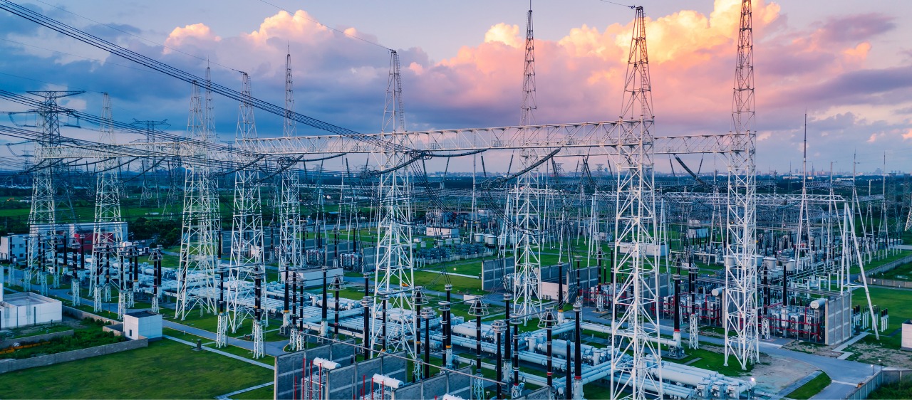
- Utility substations
- Metro rail projects
For example, a large manufacturing facility operating a 5 MVA load continuously can lose lakhs of rupees annually if transformer efficiency is reduced by even 1%.
Small design decisions create significant long-term operational impacts.
Powertech Power Transformer Product Range
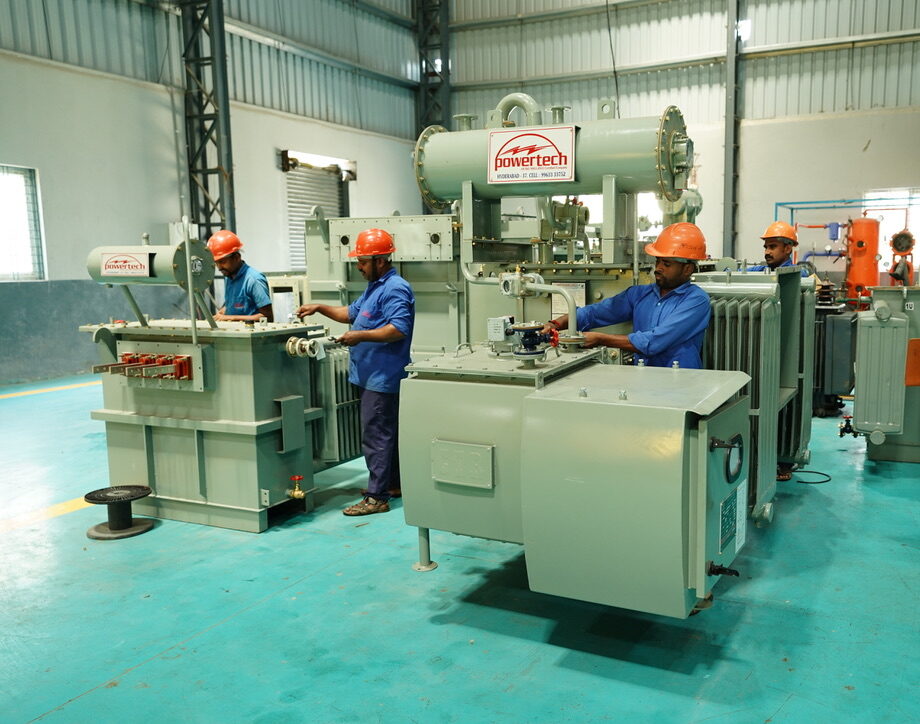
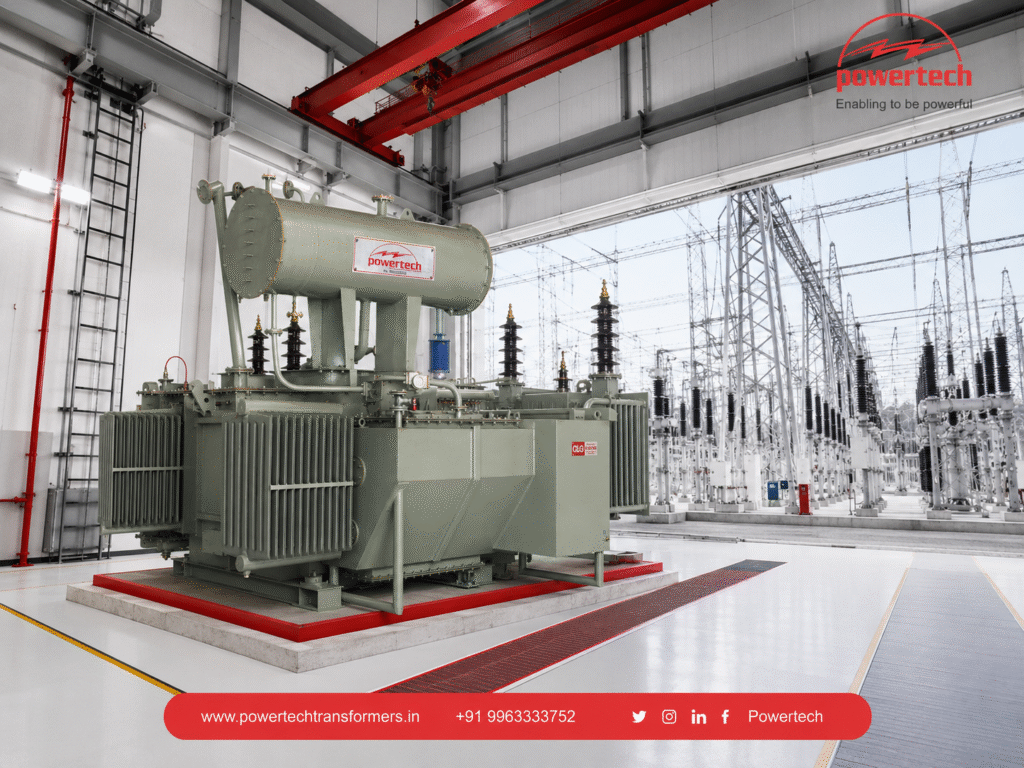
As experienced Power Transformer Manufacturers in Hyderabad, Powertech designs and manufactures transformers for demanding industrial environments.
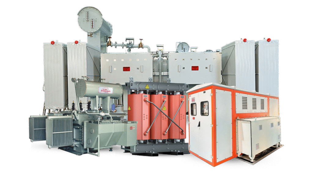
Our product range includes:
- Oil Cooled Power Transformers
- Distribution Transformers
- Dry Type Transformers
- Solar Inverter Duty Transformers
- Compact Substations
- Oil Cooled CTs and PTs
- Cast Resin CTs and PTs
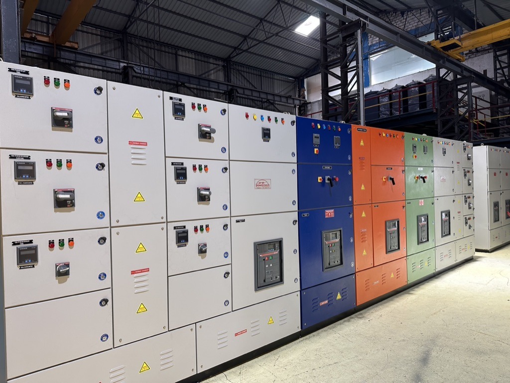
- HT and LT Panels
Our manufacturing capabilities currently cover:
- Ratings from 25 kVA to 20 MVA
- Voltage class up to 33 kV
- Custom solutions for industrial, infrastructure, and renewable energy applications
With over 25 years of manufacturing expertise, our focus remains the same:
Deliver reliable equipment that industries can trust for decades.
Key Takeaways
If you remember only three things from this guide, remember these:
- Transformers work using electromagnetic induction, not physical electrical connection.
- Core design, winding design, and cooling method directly impact performance and lifespan.
- Transformer efficiency has a major impact on long-term operating costs.
Choosing the right transformer is not simply a purchase decision.
It’s an infrastructure decision that can affect reliability, maintenance costs, and energy consumption for the next 25 years.
Contact Powertech for a Free Consultation
Selecting the right transformer configuration for your project can significantly improve efficiency, reliability, and lifecycle costs.
Whether you’re designing a manufacturing facility, upgrading a substation, or planning a renewable energy project, our engineering team can help.
Contact Powertech for a free consultation today.
📞 Phone: +91 9963333752